Voltage multipliers are electronic circuits designed to convert an alternating current (AC) input into a higher direct current (DC) voltage. By utilizing diodes and capacitors in specific configurations, these circuits “multiply” the input voltage without the need for bulky transformers. This article explores the principles, types, design considerations, applications, and limitations of voltage multipliers.
Basic Principle
Voltage multipliers operate by charging capacitors during alternating half-cycles of the input AC voltage and then connecting them in series to sum their voltages. The diodes control the charging direction, ensuring each capacitor charges to the peak input voltage (Vp) and transfers its charge to subsequent stages. The result is a DC output voltage that is a multiple of the input peak voltage.
Types of Voltage Multipliers
1. Voltage Doubler
Circuit: Two diodes and two capacitors.
Operation:
Negative Half-Cycle: C1 charges to Vp via D1.
Positive Half-Cycle: C2 charges to Vp through D2, adding to C1‘s voltage. Output: 2Vp.
Applications: Low-power devices like CRT monitors.
2. Voltage Tripler
Circuit: Three diodes and three capacitors.
Operation:
Stage 1: C1 charges to Vp.
Stage 2: C2 charges to 2Vp.
Stage 3: C3 charges to 3Vp.
Output: 3Vp. Used in laser systems and ion pumps.
3. Voltage Quadrupler
Circuit: Four diodes and four capacitors.
Operation: Extends the tripler principle, with each stage adding Vp.
Output: 4Vp. Common in electrostatic precipitators.
4. Cockcroft-Walton Multiplier
Structure: A ladder network of diodes and capacitors.
Operation: Each stage adds Vp, with n stages producing n×Vp.
Applications: Particle accelerators, X-ray machines.
Key Components
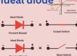
Diodes: Must withstand peak inverse voltage (2Vp in most configurations) and forward current.
Capacitors: Selected for voltage rating (>Vp) and capacitance (minimizes ripple).
Resistors: Optional for current limiting or discharging capacitors.
Design Considerations
Load Current: Higher current increases voltage drop (Vdrop=IloadfC) and ripple.
Frequency: Higher frequencies reduce ripple and allow smaller capacitors.
Efficiency: Decreases with each stage due to diode drops and capacitor ESR.
Ripple Voltage:
For half-wave: Vripple=IloadfC.
For full-wave: Vripple=Iload2fC.
Applications
CRT Displays: Anode voltages (10–30 kV).
Laser Systems: High-voltage pulse generation.
Photocopiers: Electrostatic charging.
Scientific Equipment: Particle accelerators, mass spectrometers.
Advantages and Limitations
Pros:
Compact, transformerless design.
Cost-effective for high-voltage, low-current needs.
Cons:
Poor voltage regulation under load.
Limited current capacity.
Efficiency declines with added stages.
Safety and Practical Tips
High Voltage Risks: Use insulation and bleeder resistors to discharge capacitors.
Component Selection: Diodes and capacitors must exceed expected voltage/current.
Testing: Start with low-voltage AC and verify each stage.
Historical Context
The Cockcroft-Walton multiplier, developed in 1932, enabled the first artificial nuclear disintegration. This breakthrough underscored the importance of voltage multipliers in scientific research.
Future Trends
Integration: Miniaturized multipliers in ICs for medical devices.
High-Frequency Designs: Improved efficiency with smaller components.
Conclusion
Voltage multipliers are indispensable for generating high DC voltages efficiently. While they lack the current capacity of transformers, their simplicity and compactness make them ideal for specialized applications. Advances in semiconductor technology continue to expand their utility in modern electronics.

- Everything You Need To Know About Limit Switch - May 21, 2025
- Everthing You Should Know About Rheostat - May 20, 2025
- Everything You Need To Know About Reversing Contactor - May 19, 2025