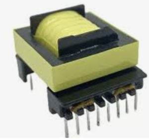
A flyback transformer (FBT), also known as a line output transformer (LOPT), is a critical component in high-voltage power conversion systems. Historically prominent in cathode-ray tube (CRT) televisions and monitors, it generates the ultra-high voltages (15–30 kV) required to accelerate electrons toward the CRT screen. Today, flyback transformers are integral to switch-mode power supplies (SMPS), LED drivers, automotive systems, and renewable energy applications. This article explores their structure, operation, design considerations, and modern uses.
Structure and Components
A flyback transformer differs from conventional transformers by its dual role as an inductor and transformer. Key components include:
Core: Typically ferrite due to high resistivity, low eddy current losses, and ability to operate at high frequencies. The core often includes an air gap to store magnetic energy and prevent saturation.
Windings:
Primary Winding: Connected to a switching transistor (e.g., MOSFET) that controls energy storage.
Secondary Winding: Delivers energy to the load, often with a high turns ratio (e.g., 1:100) for voltage step-up.
Additional windings may provide feedback or auxiliary voltages.
Insulation: Critical for high-voltage applications (e.g., CRTs), using materials like epoxy or triple-insulated wire to prevent arcing.
Built-in Components: Some FBTs integrate rectifier diodes, voltage multipliers, or focus/screen controls for CRTs.
Working Principle
Flyback transformers operate in discontinuous conduction mode (DCM) or continuous conduction mode (CCM), depending on energy transfer timing. The core process involves:
Energy Storage Phase:
The primary switch (e.g., MOSFET) turns on, allowing current (Ip) to flow through the primary winding.
Energy (E=0.5⋅Lp⋅Ip2) is stored in the core’s magnetic field.
Energy Transfer Phase:
The switch turns off, collapsing the magnetic field and inducing a voltage in the secondary winding (Vs=Vp⋅NsNp).
The secondary diode conducts, transferring energy to the load via the output capacitor.
Key Equations:
Peak primary current: Ipeak=Vin⋅DLp⋅fsw
(where D = duty cycle, fsw = switching frequency)Output voltage (DCM): Vout=Vin⋅NsNp⋅D2LpRload⋅Tsw
Key Design Considerations
Core Selection: Ferrite cores with an air gap optimize energy storage and minimize losses. Core size depends on power and frequency.
Turns Ratio: Dictates voltage transformation. High ratios (e.g., 1:100) are used for CRTs, while lower ratios suit SMPS.
Switching Frequency: Higher frequencies (50 kHz–1 MHz) reduce component size but increase core losses.
Leakage Inductance: Minimized via interleaved windings to improve efficiency. Snubber circuits (e.g., RCD networks) clamp voltage spikes.
Insulation and Safety: Creepage/clearance distances, potting materials, and certifications (e.g., UL, IEC) ensure reliability.
Thermal Management: Core losses (Pcore∝fsw1.3) and copper losses require heat sinks or forced cooling.
Applications
CRT Displays: Generate anode voltage (20–30 kV) and focus/screen voltages.
Switch-Mode Power Supplies: Isolated DC-DC converters in chargers, adapters, and industrial systems.
LED Lighting: Drive LEDs with constant current in automotive and architectural lighting.
Automotive: Ignition systems, electric vehicle DC-DC converters, and infotainment power supplies.
Renewable Energy: Inverters and charge controllers for solar/wind systems.
Advantages and Disadvantages
Advantages:
Compact size and cost-effectiveness for high-voltage applications.
Galvanic isolation enhances safety.
Flexible output voltage control via duty cycle.
Disadvantages:
Electromagnetic interference (EMI) from switching.
Complex design due to leakage inductance and snubber requirements.
Core saturation risks if improperly designed.
Troubleshooting and Testing
Common Failures:
Shorted windings from insulation breakdown.
Open circuits due to solder joint fatigue.
Core cracking or saturation.
Testing Methods:
Resistance Checks: Use a multimeter to detect open/short circuits.
Insulation Resistance: Megger testing (≥1 kV) between windings and core.
Waveform Analysis: Oscilloscope monitoring of primary switching and secondary output.
Hipot Testing: Validate dielectric strength at high voltages.
Safety: Discharge capacitors before handling; use personal protective equipment (PPE).
Future Trends
Wide Bandgap Semiconductors: Gallium nitride (GaN) and silicon carbide (SiC) transistors enable higher efficiency and frequencies.
Digital Control: Microcontroller-based feedback loops for precise regulation.
Advanced Materials: Nanocrystalline cores for reduced losses.
Integration: Monolithic flyback ICs with built-in switches and control logic.
Conclusion
Flyback transformers remain vital in modern electronics, bridging high-voltage needs with compact design. From their CRT origins to cutting-edge power supplies, understanding their operation and design nuances is essential for engineers. As technology advances, innovations in materials and control systems will further enhance their efficiency and application scope.
- Everything You Need To Know About Limit Switch - May 21, 2025
- Everthing You Should Know About Rheostat - May 20, 2025
- Everything You Need To Know About Reversing Contactor - May 19, 2025


