Relays are essential components in electrical systems, enabling low-power circuits to control high-power devices. This guide covers relay wiring for various pin configurations, including step-by-step instructions, diagrams, and practical tips.
1. Introduction to Relays
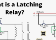
A relay is an electromagnetic switch that isolates two circuits: a control circuit (coil) and a load circuit (contacts). When the coil is energized, it creates a magnetic field that toggles the contacts, opening or closing the load circuit.
Common Applications:
Automotive systems (headlights, fans)
Home automation (lighting, HVAC)
Industrial machinery (motor controls, safety interlocks)
2. Understanding Relay Terminology
SPST (Single Pole Single Throw): One circuit controlled, two contacts (NO or NC).
SPDT (Single Pole Double Throw): One common contact, two outputs (NO and NC).
DPDT (Double Pole Double Throw): Two separate SPDT circuits controlled by one coil.
Coil Pins: Activate the relay when powered (typically labeled 85, 86 or A1, A2).
NO (Normally Open): Contact closes when the coil is energized.
NC (Normally Closed): Contact opens when the coil is energized.
COM (Common): Central contact that switches between NO and NC.
3. Relay Types and Pin Configurations
A. 4-Pin Relay (SPST)
Function: Controls a single circuit (NO only).
Pin Diagram:
85 & 86: Coil terminals.
30: COM (input).
87: NO (output).
Wiring Steps:
Connect 85 to ground.
Connect 86 to a switch, then to power.
Link 30 to the power source for the load.
Connect 87 to the load (e.g., light, motor).
Example Use: Automotive headlight control.
B. 5-Pin Relay (SPDT)
Function: Switches between NO and NC.
Pin Diagram:
85 & 86: Coil terminals.
30: COM.
87: NO.
87a: NC.
Wiring Steps:
Connect 85/86 to the control circuit.
30 to the power source.
87 to the NO load (activates when coil is powered).
87a to the NC load (deactivates when coil is powered).
Example Use: Fail-safe circuits (e.g., backup lights when primary fails).
C. 8-Pin Relay (DPDT)
Function: Controls two independent SPDT circuits.
Pin Diagram:
Pins 1–8: Two coils (pins 1–2 and 5–6), four contacts (pairs of COM, NO, NC).
Wiring Steps:
Connect coils (e.g., pins 1–2 and 5–6) to separate control circuits.
Wire COMs (pins 3, 7) to power sources.
NO/NC contacts (pins 4, 8 and others) to loads.
Example Use: Reversing motor polarity.
D. Solid-State Relay (SSR)
Function: No moving parts; uses semiconductors.
Pin Diagram:
Input (+/-): Low-voltage control (3–32V DC).
Output (Load +/-): High-voltage load (up to 480V AC).
Wiring Steps:
Connect input to a DC control source (e.g., microcontroller).
Link output to the AC/DC load.
Add a heat sink if handling high currents.
Example Use: Silent switching in HVAC systems.
4. Step-by-Step Wiring Guide
Tools Needed:
Multimeter
Wire strippers
Screwdrivers
Relay socket (optional)
General Steps:
Identify Pins: Use a multimeter to test continuity/resistance. Coil pins typically have 50–120Ω resistance.
Connect Control Circuit: Wire the coil to a switch and power source.
Wire Load Circuit: Attach COM to power, NO/NC to the load.
Test: Energize the coil to verify switching.
5. Troubleshooting & Safety
Common Mistakes:
Incorrect coil voltage (check ratings).
Reversing NO/NC contacts.
Overloading contacts (exceeding current ratings).
Safety Tips:
Always de-energize circuits before wiring.
Use fuses to protect control circuits.
Match wire gauge to the load current.
6. Conclusion
Understanding relay pin diagrams is critical for safe and effective wiring. Whether using a 4-pin SPST relay for simple tasks or a DPDT relay for complex systems, always consult the datasheet and double-check connections. With this guide, you’re equipped to tackle relay wiring across diverse applications!
Pro Tip: Label wires and document your setup for future troubleshooting.

- Everything You Need To Know About Limit Switch - May 21, 2025
- Everthing You Should Know About Rheostat - May 20, 2025
- Everything You Need To Know About Reversing Contactor - May 19, 2025