Timer integrated circuits ( ICs) are versatile components used to generate precise time delays, oscillations, and pulse-width modulation (PWM) signals. Among them, the NE555 (and its variants) is one of the most iconic ICs in electronics history. This guide explores timer IC types, applications, design principles, and selection criteria.
Table of Contents
Toggle1. What Is a Timer IC?
A timer IC is a semiconductor device designed to produce accurate timing intervals or oscillate at specific frequencies. It simplifies circuit design by integrating analog and digital components like comparators, flip-flops, and output drivers.
2. Common Timer IC Types
| Model | Key Features | Applications |
|---|---|---|
| NE555 | Classic bipolar design, 4.5–16V supply, ±200mA output | Pulse generation, delays, oscillators |
| TLC555 | CMOS version, 2–15V supply, low power ( <1mW) | Battery-powered devices |
| LMC555 | Rail-to-rail output, 1.5–15V supply | Low-voltage systems |
| ICM7555 | Improved CMOS, reduced supply current (60µA) | Precision timing |
| TS556 | Dual 555 timer in one package | Complex multi-timing circuits |
| Programmable Timers (e.g., TPL5110) | Adjustable timing via resistors or digital interfaces | IoT, wake-up circuits |
3. Key Parameters for Selection
Electrical Specifications
- Supply Voltage (V<sub>CC</sub>): Ranges from 1.5V (LMC555) to 16V (NE555).
- Output Current: ±200mA for NE555 vs. ±50mA for CMOS variants.
- Timing Accuracy: ±1–3% for standard 555; ±0.5% for precision models.
- Frequency Range: Up to 3MHz for advanced CMOS timers.
Timing Formulas
- Monostable Mode (One-Shot): T=1.1×R×CT=1.1×R×C
- Astable Mode (Oscillator): f=1.44(R1+2R2)×C,Duty Cycle=R1+R2R1+2R2f=(R1+2R2)×C1.44,Duty Cycle=R1+2R2R1+R2
4. Applications & Circuit Configurations
Common Use Cases
- Pulse Generation: Triggering sensors, stepper motors, or relays.
- Oscillators: Clock signals for microcontrollers or LED flashers.
- PWM Control: Motor speed regulation, LED dimming.
- Voltage-Controlled Oscillators (VCO): Frequency modulation via control voltage.
Design Example: 1-Minute Delay (Monostable)
- Choose C=100μFC=100μF.
- Solve for RR: R=60s1.1×100μF≈545kΩ(use 510kΩ + 33kΩ resistors)R=1.1×100μF60s≈545kΩ(use 510kΩ + 33kΩ resistors)
5. Design Considerations
Component Selection
- Capacitors: Use low-leakage types (ceramic or tantalum) for timing accuracy.
- Resistors: Stay within 1kΩ–10MΩ for stable operation.
- Bypass Capacitor: Add 0.1µF across V<sub>CC</sub> and GND to reduce noise.
Thermal & Noise Management
- Avoid placing high-current traces near timing components.
- For high frequencies (>100kHz), use SMD components to minimize parasitic inductance.
6. Advanced Techniques
- Precision Adjustments: Add a potentiometer to fine-tune timing.
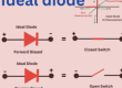
- Duty Cycle Control: Insert a diode parallel to R2R2 in astable mode for 50% duty cycle.
- Cascading Timers: Connect multiple 555 ICs for extended delays or complex sequences.
7. Troubleshooting Common Issues
| Issue | Solution |
|---|---|
| No Output | Check trigger pulse (>2V for NE555), verify power supply |
| Unstable Timing | Replace electrolytic timing capacitor with ceramic/tantalum |
| Overheating | Reduce output current; add a MOSFET/buffer for high-power loads |
| Incorrect Frequency | Verify resistor/capacitor values; check for floating control voltage pin |
8. Selection Criteria
- Voltage Range: Match V<sub>CC</sub> to your system (e.g., 3.3V systems need LMC555).
- Output Drive: For >100mA loads, use NE555; for low power, choose CMOS.
- Precision: Opt for ICM7555 or TLC555 if timing accuracy is critical.
- Package: Through-hole (DIP-8) for prototyping; SOT-23 for compact designs.
9. Modern Alternatives
- Microcontroller-Based Timers: Offer programmability but require coding.
- Programmable Timer ICs (e.g., TPL5110): Adjust timing via digital interfaces (I2C/SPI).
10. Industry Standards & Reliability
- Automotive: Use AEC-Q100-qualified timers for temperature resilience (-40°C to +125°C).
- Industrial: Opt for wide V<sub>CC</sub> range (e.g., TLC555: 2–15V).
Step-by-Step Design Checklist
- Define timing requirements (delay, frequency, duty cycle).
- Choose monostable/astable mode.
- Calculate R and C values using timing formulas.
- Select a timer IC based on voltage, current, and precision.
- Simulate with SPICE tools (e.g., LTspice).
- Prototype and validate with an oscilloscope.
Pro Tips
- SPICE Simulation: Model circuits before prototyping to catch errors.
- Datasheet Focus: Review “Typical Applications” section for inspiration.
- Current Limiting: Add a series resistor if driving inductive loads (e.g., relays).
By mastering timer ICs, you can simplify everything from LED blinkers to industrial automation systems. Always cross-reference manufacturer datasheets for thresholds, temperature derating, and layout guidelines.

- Everything You Need To Know About Limit Switch - May 21, 2025
- Everthing You Should Know About Rheostat - May 20, 2025
- Everything You Need To Know About Reversing Contactor - May 19, 2025