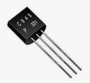
The C945 transistor, often designated as 2SC945, is a widely used bipolar junction transistor (BJT) known for its reliability in low-power applications. This article provides an in-depth analysis of its specifications, applications, and usage considerations.
1. Overview and Manufacturer Information
- Part Number: C945 (abbreviated from 2SC945, following Japanese JIS naming conventions).
- Type: NPN BJT (Bipolar Junction Transistor).
- Manufacturers: Originally produced by companies like Toshiba, now available from multiple semiconductor manufacturers (e.g., Fairchild, ON Semiconductor).
2. Key Specifications
- Collector-Base Voltage (VCBO): 60V.
- Collector-Emitter Voltage (VCEO): 50V.
- Emitter-Base Voltage (VEBO): 5V.
- Continuous Collector Current (IC): 150mA (max).
- Power Dissipation (Ptot): 250mW (at 25°C).
- DC Current Gain (hFE): 70–700 (varies with operating conditions and manufacturer).
- Transition Frequency (fT): 250MHz (typical for small-signal amplification).
- Package: TO-92 (common through-hole package).
3. Pin Configuration (TO-92 Package)
When viewing the flat side with pins downward:
- Emitter (E).
- Base (B).
- Collector (C).
Note: Always verify pinout with the datasheet, as variations exist between manufacturers.
4. Applications
The C945 excels in low-power scenarios:
- Amplification: Audio preamps, RF stages, and signal processing.
- Switching: Relay drivers, LED drivers, and digital logic circuits.
- Oscillators: Used in radio and timing circuits.
- Consumer Electronics: Found in TVs, radios, and toys due to its cost-effectiveness.
5. Equivalent and Substitute Transistors
If unavailable, consider:
- 2N3904: Similar VCEO (40V) and IC (200mA).
- BC547: Comparable voltage ratings (45V VCEO) and gain.
- 2N2222: Higher current capability (800mA) but lower gain.
- KSC945: Direct equivalent with identical specs.
Caution: Verify substitutions match voltage, current, and gain requirements.
6. Thermal and Operational Considerations
- Temperature Range: -55°C to +150°C.
- Derating: Reduce power dissipation above 25°C (e.g., 2mW/°C decrease).
- Heat Management: No heatsink needed for low-power use; avoid prolonged operation near max ratings.
7. Common Usage Mistakes
- Incorrect Pinout: Reversing emitter and collector damages the transistor.
- Overloading: Exceeding 150mA collector current or 50V VCEO risks failure.
- Insufficient Base Current: In switching, ensure IB ≥ IC/hFE to saturate the transistor.
8. Testing the C945
Use a multimeter in diode mode:
- Base-Emitter (B-E): Forward bias ~0.6V, reverse open.
- Base-Collector (B-C): Forward bias ~0.6V, reverse open.
- Emitter-Collector (E-C): Open in both directions.
9. Historical Context and Availability
- Introduced in the 1970s, the C945 became a staple in Japanese electronics.
- Still in production but less common in modern SMD-dominated designs; available through distributors like Digi-Key and Mouser.
10. Example Circuit
Simple LED Driver:
- Components: C945, 1kΩ resistor (base), LED, 5V supply.
- Operation: A microcontroller signal (3.3V/5V) to the base switches the LED via the collector-emitter path.
11. Datasheet Reference
- Always consult the manufacturer’s datasheet for precise specs (e.g., Toshiba 2SC945 Datasheet).
Conclusion
The C945 transistor remains a versatile, cost-effective solution for low-power amplification and switching. Its enduring presence in electronics underscores its utility, though designers should verify substitutes and adhere to operational limits for optimal performance.
- Everything You Need To Know About Limit Switch - May 21, 2025
- Everthing You Should Know About Rheostat - May 20, 2025
- Everything You Need To Know About Reversing Contactor - May 19, 2025


