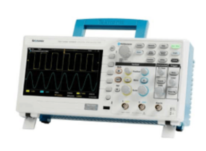
An oscilloscope, often called a “scope,” is an electronic test instrument that graphically displays voltage signals as waveforms over time. It allows engineers, technicians, and hobbyists to observe signal behavior, measure parameters like amplitude and frequency, and diagnose issues in circuits. This guide explores its history, components, types, applications, and future trends.
1. History of Oscilloscopes
- Early Developments: The first oscilloscopes emerged in the 1890s with Karl Braun’s invention of the cathode-ray tube (CRT). These analog devices plotted electrical signals on a fluorescent screen.
- Analog Era: By the 1940s, companies like Tektronix commercialized analog oscilloscopes, which dominated until the 1980s.
- Digital Revolution: The 1980s introduced digital storage oscilloscopes (DSOs), leveraging analog-to-digital converters (ADCs) to sample and store waveforms digitally.
- Modern Advances: Today’s oscilloscopes feature high-speed sampling, touchscreens, and advanced analysis tools like FFT and protocol decoding.
2. Key Components
- Display: CRTs (analog) or LCDs (digital) visualize waveforms.
- Vertical/Horizontal Systems:
- Vertical: Amplifies/attenuates input signals to fit the display.
- Horizontal: Controls the timebase (sweep speed).
- Trigger System: Stabilizes repetitive waveforms by aligning captures to a specific event (e.g., rising edge).
- Probes: Connect the device under test (DUT) to the oscilloscope. Passive (1x/10x) and active probes are common.
- ADC & Memory (Digital Scopes): Converts analog signals to digital data and stores it for analysis.
3. Types of Oscilloscopes
- Analog: Uses CRT to display real-time signals. Ideal for simple, high-frequency applications.
- Digital Storage (DSO): Stores waveforms for later analysis. Offers triggering and measurement tools.
- Digital Phosphor (DPO): Mimics analog displays with high waveform capture rates for transient events.
- Mixed Signal (MSO): Combines analog channels with digital inputs (e.g., 16 digital channels) for embedded system debugging.
- Handheld: Portable, battery-powered scopes for fieldwork.
4. Key Specifications
- Bandwidth: The maximum frequency a scope can accurately measure (e.g., 100 MHz). Rule: Bandwidth ≥ 5x signal frequency.
- Sample Rate: Samples per second (e.g., 1 GS/s). Must exceed twice the bandwidth (Nyquist theorem).
- Memory Depth: Determines how long a waveform can be captured at high resolution (e.g., 10 Mpts).
- Rise Time: Affects ability to capture fast transitions (Rise Time ≈ 0.35 / Bandwidth).
- Channels: Most scopes offer 2-4 analog channels; MSOs add digital channels.
5. Applications
- Electronics Debugging: Diagnose noise, glitches, or timing issues in circuits.
- Telecommunications: Analyze modulation in RF or serial protocols (I2C, SPI).
- Education: Teach waveform fundamentals in labs.
- Automotive: Test sensors, CAN bus signals, or ignition systems.
- Power Analysis: Measure ripple, harmonics, or switching losses in power electronics.
6. Choosing the Right Oscilloscope
- Application Needs:
- High-speed signals (e.g., DDR memory) require >1 GHz bandwidth.
- Embedded systems benefit from MSOs with protocol decoding.
- Budget: Entry-level scopes (e.g., Rigol DS1054Z: 400)suithobbyists;high−endmodels(KeysightInfiniium:30k+) offer advanced analysis.
- Portability: Handheld or USB scopes (e.g., Analog Discovery) are ideal for fieldwork.
7. Probes and Accessories
- Passive Probes: Affordable but limited to ≤500 MHz. Use 10x mode for high-voltage measurements.
- Active Probes: Higher bandwidth (≥1 GHz) but costlier. Ideal for high-speed circuits.
- Differential Probes: Measure floating voltages (e.g., motor drives).
- Current Probes: Convert current to voltage via Hall effect or Rogowski coils.
- Probe Calibration: Always compensate probes using the scope’s calibration square wave.
8. Advanced Features
- FFT (Fast Fourier Transform): Converts time-domain signals to frequency domain for harmonic analysis.
- Serial Protocol Decoding: Translates binary data into human-readable formats (UART, USB).
- Waveform Math: Perform operations (e.g., integrate, subtract) on captured signals.
- Automated Measurements: Instant readouts of frequency, rise time, and RMS voltage.
9. Safety Tips
- Grounding: Use the oscilloscope’s ground lead to avoid short circuits.
- Voltage Limits: Stay within probe ratings (typically ≤300 V).
- Isolation: For high-voltage measurements, use isolated differential probes or isolation transformers.
10. Future Trends
- Higher Bandwidths: Scopes exceeding 100 GHz for 5G and terabit Ethernet.
- Integration : Combined scopes, logic analyzers, and spectrum analyzers in one device.
- AI-Driven Analysis: Machine learning for automated fault detection.
- Portability: Compact, USB-powered scopes with cloud connectivity.
Conclusion
Oscilloscopes remain indispensable tools for electronics work, evolving from analog CRTs to sophisticated digital systems. Understanding their specifications, probes, and features ensures accurate measurements across industries. As technology advances, scopes will continue integrating AI and higher performance, empowering engineers to tackle tomorrow’s challenges.
- Everything You Need To Know About Limit Switch - May 21, 2025
- Everthing You Should Know About Rheostat - May 20, 2025
- Everything You Need To Know About Reversing Contactor - May 19, 2025


